Patternflow
Breadboard Build Guide
Build the whole thing with no custom PCB — just one snapped-off breadboard power strip and a handful of jumper wires. This guide leads with the picture, because the wiring is the hard part.
Flashing is fiddly once everything is wired into a tangle of jumpers. Connect the bare ESP32-S3 to your computer via USB-C, visit patternflow.work, and click “Flash Patternflow OS” in the Patterns section (Chrome / Edge desktop). Confirm it boots — then start the build.
Prefer Arduino IDE? See official guide Section 8.2 for board settings and upload steps.
Bill of Materials
No PCB, no SMD parts, no soldering iron. Everything plugs together with Dupont jumper wires.
| Qty | Item | Spec / Notes |
|---|---|---|
| 1× | ESP32-S3 DevKitC | N16R8 (16 MB Flash, 8 MB PSRAM), 44-pin, 25.4 mm header spacing. PSRAM required. |
| 1× | HUB75E LED matrix | 128×64 px, P2.5, 320×160 mm. Driver IC must be 74HC595, FM6126A, or FM6124. Ships with ribbon cable + power cable — both used as-is. |
| 4× | Rotary encoder (EC11) | 5-pin, with click-switch. Recommended: PEC11R-4220F-S0024. Any click-capable EC11 works — the cheap AliExpress 5-packs are fine. |
| 1× | Breadboard power rail | Snap the +/− rail strip off any standard breadboard. Only this strip is used — the main breadboard body is not needed. |
| ~40× | Dupont jumper wires | Mix of M–F and M–M. 20 cm length recommended. Color-coded packs help but any color works. |
| 1× | USB cable (sacrificial) | Any USB cable — will be cut and stripped for 5 V power input. |
| 1× | Power bank | Any standard USB power bank that fits inside the enclosure. |
| + | Tools & extras | Hot-glue gun, wire strippers, enclosure (3D-printed or cardboard — see note below). |
* No soldering required if your encoders accept Dupont leads. You will strip two power leads (USB + panel power) — a hot-glue joint is enough.
Master wiring map
Everything in its real place: four encoders in a square on the left, the ESP32-S3 in the middle (USB at top), the HUB75E lying on its side on the right with pin 1 at the top-right, and the power rail running along the bottom.
Build Steps
Prep, mount, & connect encoder grounds
Plug a short jumper onto every pin of all four encoders first — any length you have on hand is fine. Fix the encoders into the enclosure so they can’t twist while you work, placing them in a square: ENC1 top-left, ENC2 top-right, ENC3 bottom-left, ENC4 bottom-right (holding each with the 3-pin side on the left, 2-pin side on the right).
Next, snap the +/− rail off the side of a breadboard — that little strip is the only breadboard you need. Pull just the ground wires out from the encoders (labeled GND on the left and right sides of each encoder) and land them all on the ground (−) rail of the breadboard. Leave the signal legs hanging; they go straight to the ESP32 later.
↑ Ground (GND) pins on both sides of all four rotary encoders land on the Ground (−) rail of the breadboard.
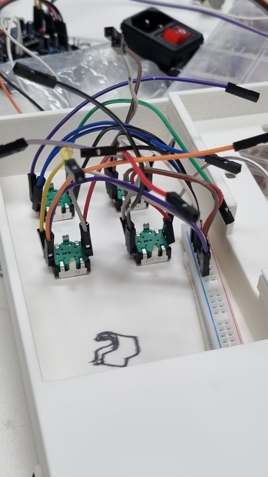
↑ Encoders fixed, GND wires on the − rail.
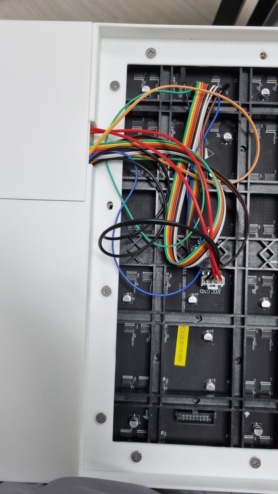
ESP32 ↔ HUB75E (the colored numbers)
This is the big one — do it next while your wires are still tidy. If your ribbon of long jumpers is fresh, peel it into strips of 8 and only separate the very ends; the bundle stays neat. Go one row at a time: connect the red numbers (1→8) first, then the blue numbers (1→6). The two Ground pins (GND) on the bottom row connect directly to the ground (−) rail on the breadboard—you can plug them into any available holes along the ground column.
↑ U1 (ESP32-S3) on the left, and J1 (HUB75E) on the right. Wire the pins that share the same color-coded labels (e.g. R1, B1, A, B...).
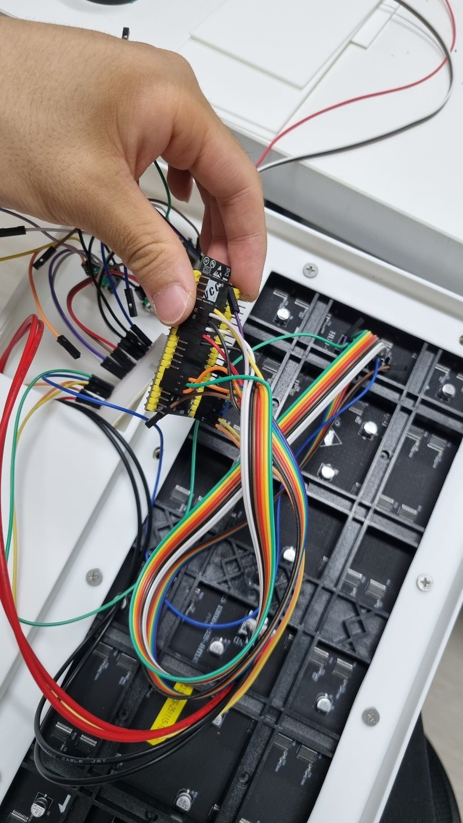
↑ ESP32-S3 with HUB75E jumpers connected.
Encoder signals → ESP32
Now land the signal legs you left hanging. Work by signal type, not by encoder — all four A’s, then all four B’s, then all four SW’s. The pins sit together on the board that way, so the wiring stays orderly. (Bonus: the four A’s land on consecutive pins 4·5·6·7.)
↑ Four rotary encoders on the left, and ESP32 on the right. Wire the signal channels (A, B, SW) to their matching colored tags (e.g. 1A, 2A...).
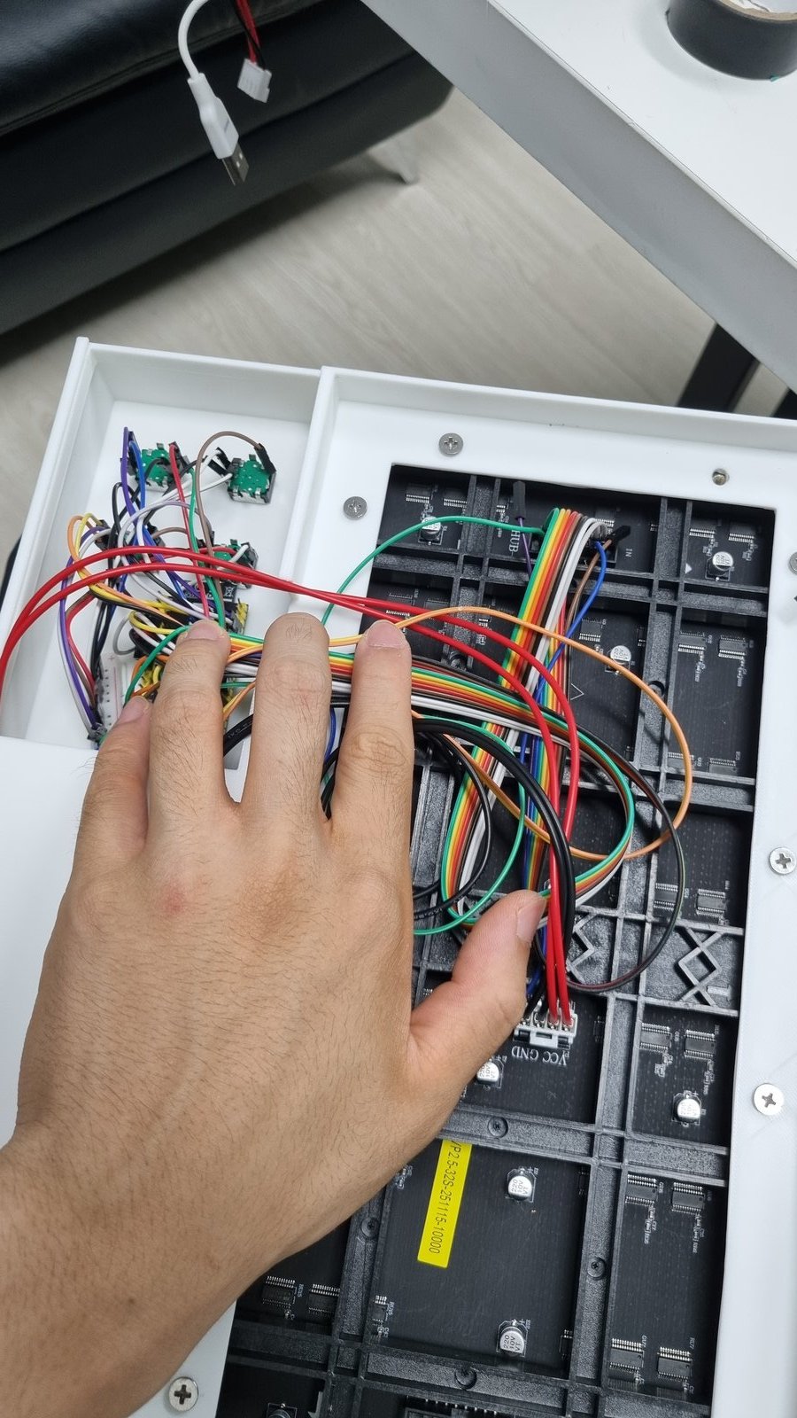
↑ Encoder A, B, SW wires all connected.
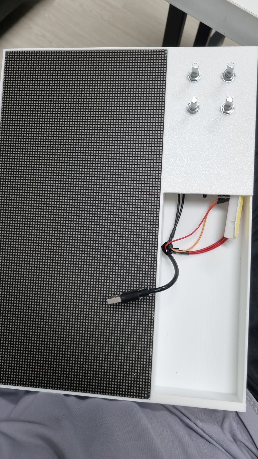
Power it
Strip the LED panel’s thick power leads and strip any spare USB cable. Twist each onto a jumper — red to +, black to − — and push them into the rail. The ESP32’s own 5V and GND pins tie into the same two rails, so one 5 V supply feeds everything. A dab of hot glue keeps the bare joints from slipping.
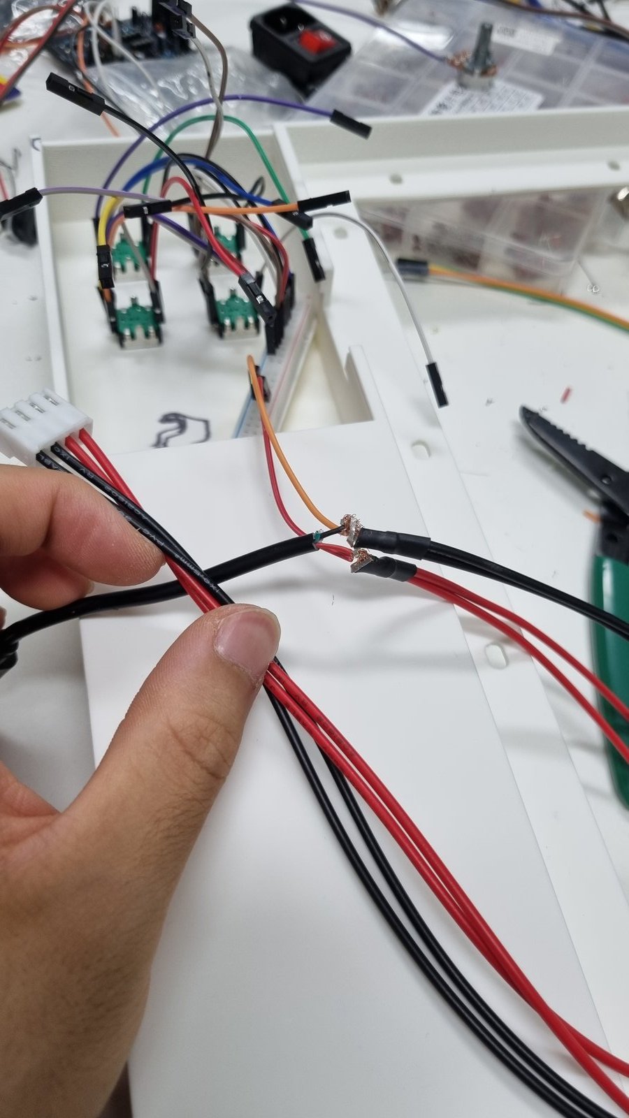
↑ Power leads stripped and twisted onto jumpers.
Close the case
Tuck the rail and the wire bundles down, seat the LED panel against the front window, and put the lid on. Plug in the supply — the matrix should light up and the encoders should respond. That’s a full Patternflow with zero custom hardware.
Tuck wires flat.
Put the lid on.
Plug in power bank.
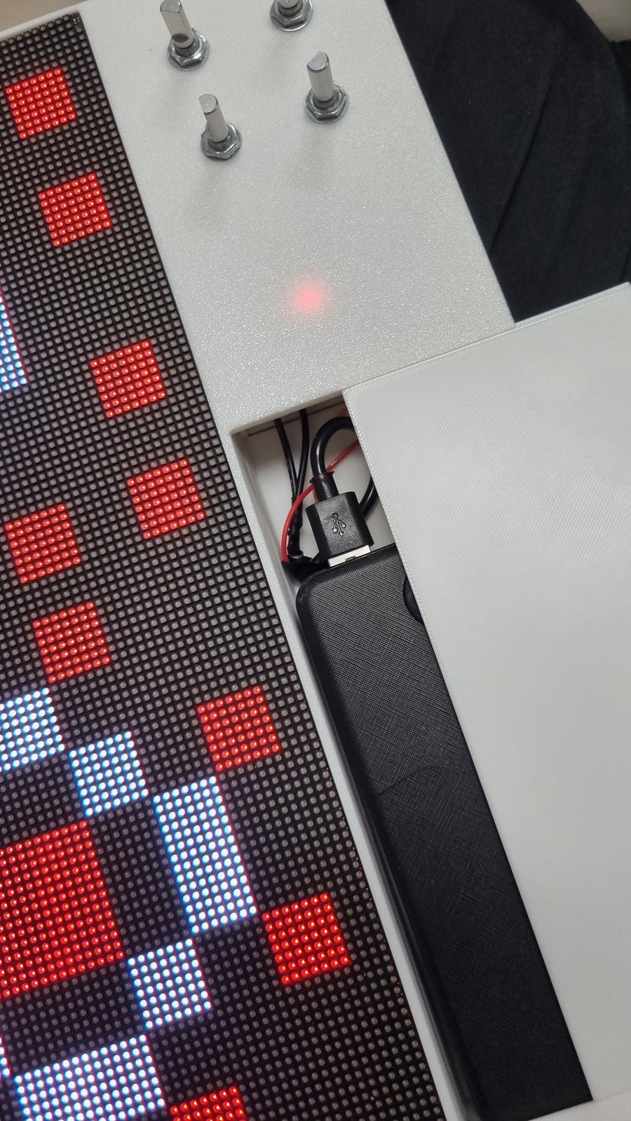
It's alive! 🎉
📖 Official Build Guide — For 3D printing, case bonding, PCB assembly, known issues, and troubleshooting, see the full guide:
github.com/engmung/Patternflow — BUILD_GUIDE.md ↗